Notes on ergodox construction
14 Aug 2014It’s dangerous to solder alone !
This post builds on the ErgoDox Assembly Instructions provided by Massdrop. As such it references components that are part of the Massdrop kit. All images are copyright Massdrop
While Massdrop’s instruction page is pretty solid, there a couple of places where it’s lacking or confusing and makes it easy to slip up. I’ve listed them in the order that you would face them during construction. Before proceeding, I’d like to include some links that might be helpful in the construction process.
- EEV blog has a great tutorial on soldering if you’re new or just rusty. Part 1 is an introduction to soldering equipment, Part 2 covers soldering and Part 3 covers surface mount soldering (required for the diodes, which is the first thing you solder).
- There is a complete Ergodox assembly video by user WhiteFireDragon available here, however there are no instructions included and it is not real time.
- The Teensy controller currently provided in the Massdrop kit is the Teensy 2.0 (atmega32u4), not the Teensy++ 2.0
Now for the actual keypoints :
- You want to use a thinner solder for the surface mount diodes and the USB mini plug than you would for the other components. .032” is a good thin solder.
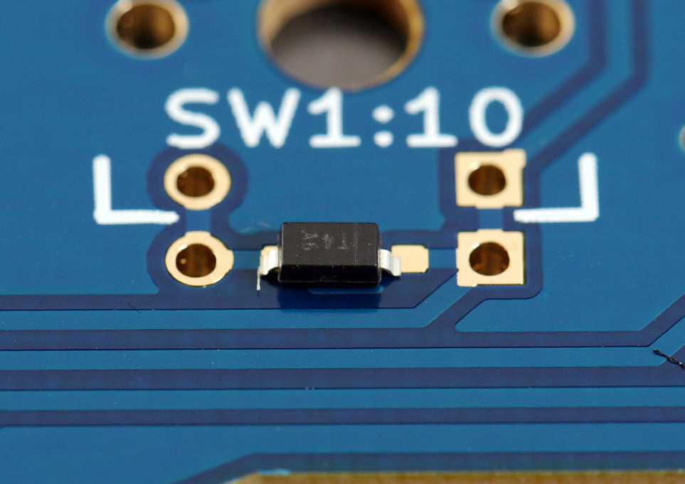
- The diodes are directional, you want the cathode (marked with a line) facing the side with the square pad (the through-hole with the square frame), as show in the image here. The diodes are also the only components that go on the underside of the PCB.

-
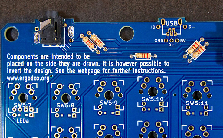
The resistors are also directional, align them as shown in the image below using the coloured lines as reference.Welp, resistors are not directional, but picking an alignment will make it easier for you to read the color codes.

- The MCP23018 I/O expander (which is also directional) has three unused pins on the lower side. These are obvious as the holes on the PCB have no copper casing on them, don’t try and solder these as there is no base to heat up.
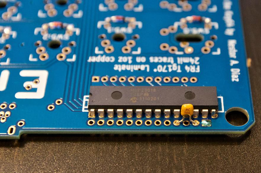
- If you solder the capacitor on to clean the signal, make sure you short the pins next to it as show in the image below, the capacitor does not work without this. Note the bit of solder shorting the pins to the right of the capacitor.

- You can use the extra bit of wire that you trim from the resistors and the capacitor to short the connections with the white outline which is required by the TRRS connectors.
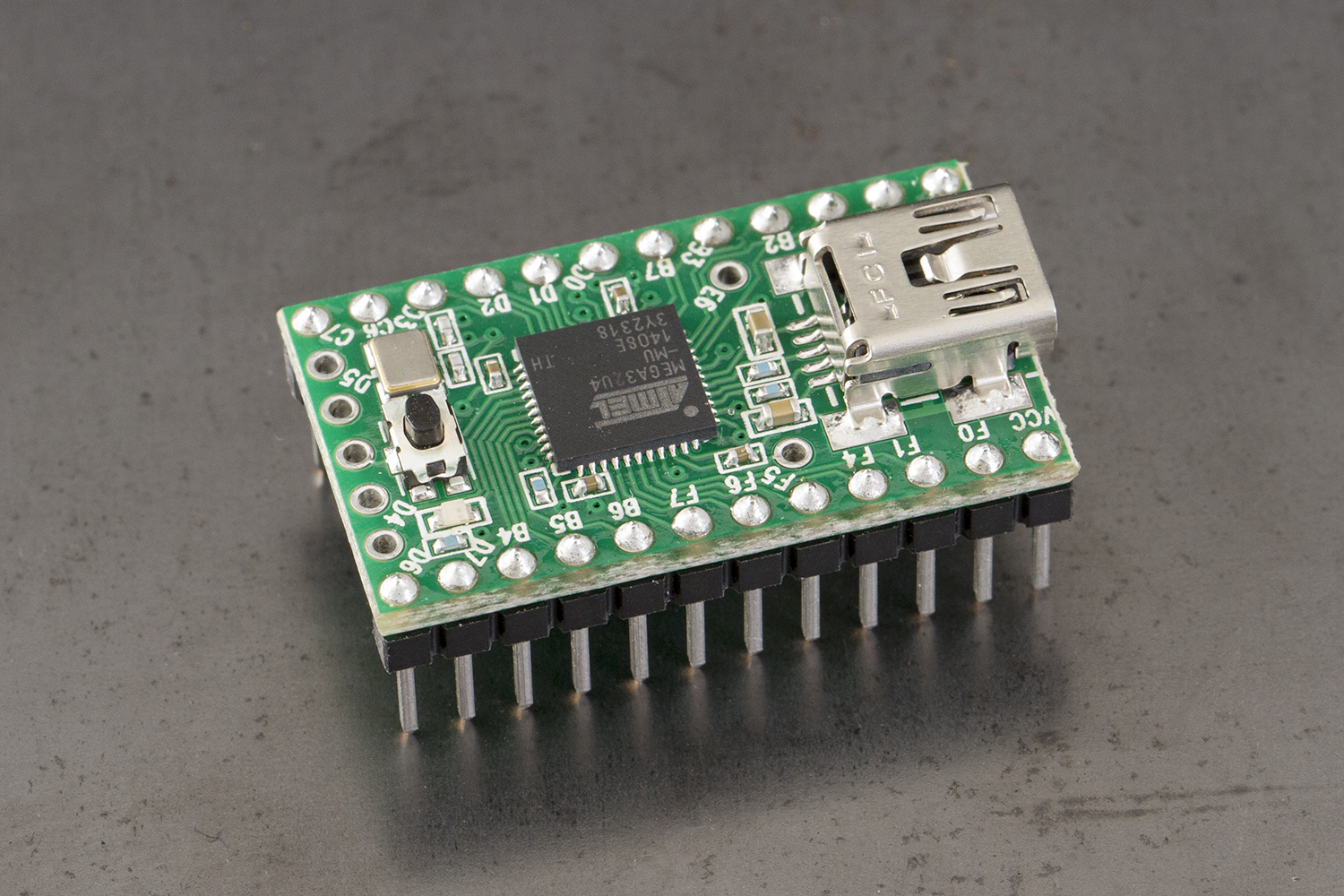
- Do not remove the black plastic spacer below the Teensy controller, it is required to provide clearance between the Teensy and the PCB. Note the black plastic spacer seen right below the Teensy in the image below.

- After you connect the USB mini connector, make sure you solder it on both sides where applicable for stability.
- You need to put Layer #3 onto the PCB before you start soldering the switches. The switches hold the plate in place and need to be put above the plate.
- The LEDs are also directional. The long end is aligned to the square pads, same as the diodes.
- Cherry MX switches can be separated into two pieces, however you will not be able to do this for the 3 switches that have LEDs on them unless you modify the switch tops, as detailed here
- You need to trim the legs of the Teensy, the resistors, the capacitor and anything else that is sticking out before you can put on the bottom of the case (Layer #1).
- Layer #5 (as provided by massdrop) actually has a hole you can use to access the teensy reset button, so you don’t need to take it off to reset the teensy.